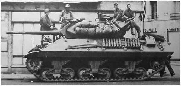
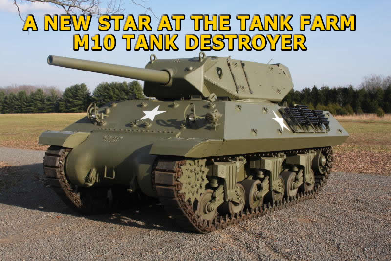
M10 Tank Destroyer Restoration Project
THE RE-BUILD IS FINISHED
ARMAMENT:
76 MM
CREW 5 WEIGHT 28.6 Tons LENGTH 19ft 7in (With Gun) WIDTH 10ft HEIGHT 8ft 2in POWER PLANT 2 GM S6-71 DIESELS SPEED 30 MPH RANGE 200 Miles |
|
M10 BREAK DOWN
|
||
Bob Bruggeman holding down the gun tube so the gun can be removed from the turret. | With the gun removed it will be a tough job to remove it from the mantelet. | Removing the mantelet from the gun tube took a lot of heat and pounding. |
With the gun removed, now it is time to lift off the turret. | Robert lifting off the turret using a large fork lift. | The hull is ready to pull into the shop to be stripped of running gear. |
The turret is removed and now ready for sand blasting. You can see the M10 tracks in the back ground. | Another view of the turret , the pins mount the mantelet which mounts the 3 inch gun. |
Looking
down the left side with first two sets of road wheels removed.
|
View of right side, engines and drive will be removed so the hull can be sand blasted. | Top view showing turret ring and gear teeth that are used to rotate the turret. |
Seats, steering levers, engine controls have been removed. The transmission and final drive need to removed. |
The twin GM S6-71 Diesels will be removed. | John Billeter and Marc Sehring removing a set of road wheels. |
The
road wheels are loaded by a set of vertical volute springs that allow
the road wheels movement.
|
Robert Toles and John Billeter taking apart a road wheel set. Care must be exercised as the springs decompress parts can be hurled with force. | The springs removed from road wheel sets. After 60 years of being compressed they were still very strong. | Track drive sprocket removed from the final drive. |
Removing the hubs from the final drive proved to be a tough job. After heating and pounding they finally gave in. | The final drive gear cluster now off lets us see the final drive train. About 30 gallons of oil had to be drained off. | A view of the track brake on the final drive. |
The track brake. As the brake is applied power is transferred to the other track through the differential gear train causing the tank to turn. | Looking in the final drive cavity, notice the differential gears. | Final drive hubs and reduction gear assembly ready to be cleaned and serviced. |
Robert connecting a chain hoist to remove the transmission. | John prying off the bow which had almost fused to the hull. | With the bow removed the transmission can now be removed. |
As
the restoration progresses we will add more pictures.
|
||
Looking at the rear of the bow with the differential exposed. Bearings will now be tested and replaced if needed. |